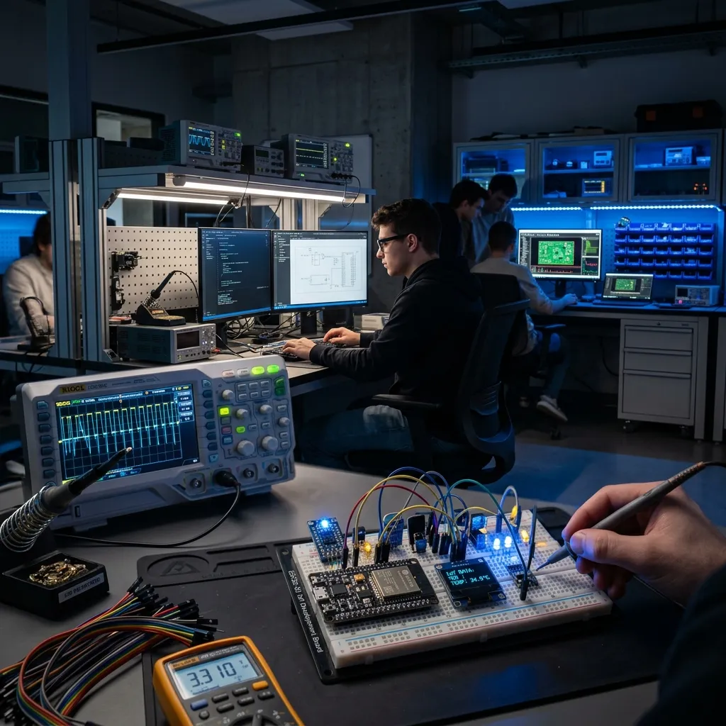
Production testing is decided at layout time. If the only way to flash a board is to solder wires to it, or the only way to check a rail is to hold a probe on a via, the test will be slow and operators will skip steps. A board designed for a jig can be dropped on pogo pins, flashed, checked and sorted into pass or fail in about two minutes.
Test points
We put a test point on every supply rail, on ground in several places, and on the signals the test needs: UART, reset, boot-mode pins, and any analog node a firmware self-test cannot read. Round pads of 1.0 to 1.5 mm work well with standard pogo pins. Keep them on one side of the board, on a grid, at least 2.54 mm apart, with a clear area around each so the probe does not land on a via or a component edge.
Two or three tooling holes or a fiducial pair give the fixture an alignment reference, and a board edge the jig can clamp against.
Programming header
Do not rely on a connector that will not be fitted in production. For ARM Cortex-M parts a footprint-only SWD interface (SWDIO, SWCLK, reset, ground, and target voltage) lets pogo pins or a spring-probe cable flash the board. For ESP32 modules, the UART pins, EN and GPIO0 are enough to enter the bootloader. Check the strapping pins described in the note on ESP32 strapping pins so the jig does not hold one at a wrong level.
The fixture
A bed-of-nails fixture presses the board onto spring probes with a lever or a pneumatic cylinder. Power comes through the fixture, ideally through a current-limited supply so a shorted board trips a limit and does not burn anything. A few opto-isolated I/O lines let the fixture trigger buttons and read LEDs.
A test sequence that fits in two minutes
- Apply power with a current limit and measure idle current.
- Check each rail voltage within its tolerance.
- Flash the firmware and verify the checksum.
- Run the firmware self-test over UART: sensors, memory, radio, relays.
- Write the serial number and calibration values, then print the label.
Every step logs a result with the serial number to a file or database. Steps that rarely fail run last, and a fail stops the sequence.
What a jig does not cover
A fixture tests the board, not the product. It will not find a bad antenna match in the enclosure, a loose connector at the other end of a cable or a thermal problem that appears after hours of running. Those need a sampling test on the finished unit.
If you are planning production and want a board and a test station that fit together, book a discovery call and see how we approach production support and PCB design.